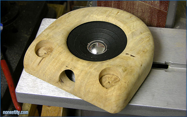
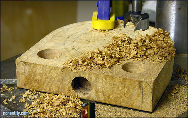
Finally got the speaker cavity routed out enough to fit the speaker AND
the input jack. It's taking a lot of effort to get enough room for
all the components.
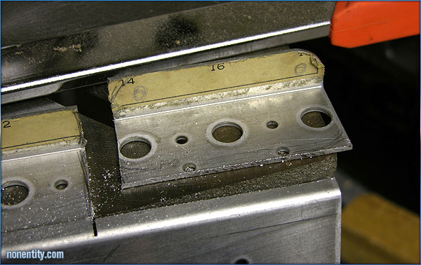
The tolerances are so close that I have to remove most of the wood that
would normally hold the input jack in place. I will have to make a
bracket for the input jack. I am using this section of some chassis
from a discarded test gadget.
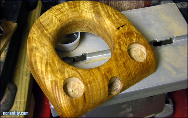
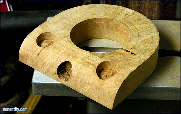
Can't wait to get this one done, I love how the grain drapes over the
shape of this amp.
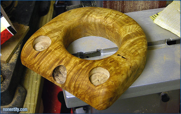
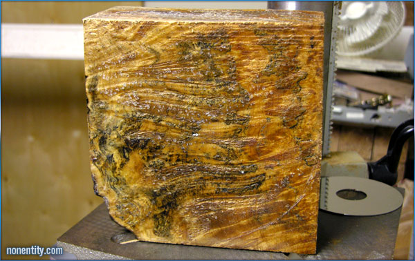
A few passes with some sandpaper, later, and a nice wash in mineral
spirits to see how it's going to turn out.
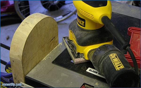
Router work done (first pass at least) Time for some hand sanding.
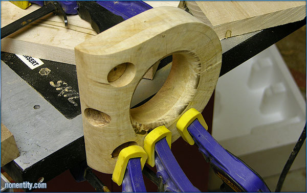
Clamped up for routing the bevel on the side.
After clamping the block between two sticks that are wide enough so I can
get my router to the speaker hole, I carefully round out the speaker
bevel.
Used the belt sander to peel the curve into the control face.
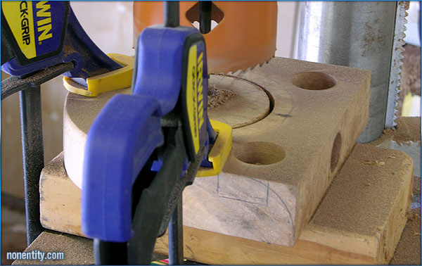
Here's the final hole and plug! I can use the plug for something I
am sure, shape it on the lathe or whatever. At least it wasn't
wasted as shavings on the floor from a forstner bit.
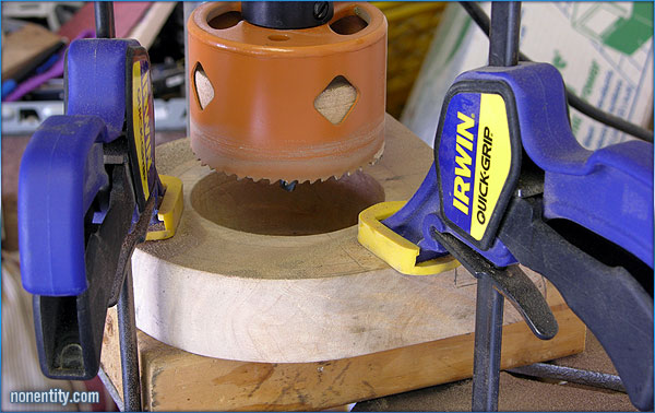
After a couple minutes of sheer pain as a particularly horrendous high
pitched shriek from the bad harmonics of the hole saw cutting through this
much dense wood. Ow, my ears are still sore from that.
Test cut of a couple millimeters to make sure it's in the right spot.
I am using a 3 inch hole saw chucked into my drill press to make the main
speaker hole of the amp.
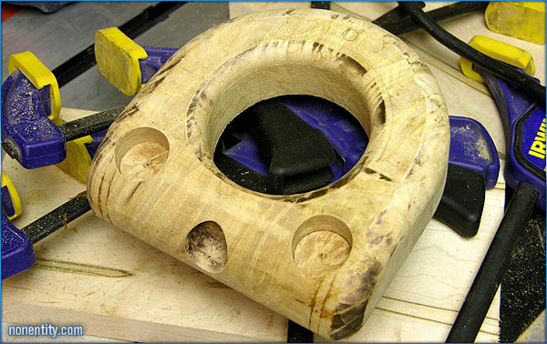
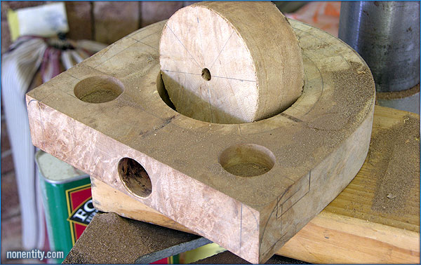
The knob and input jack holes drilled. I learned on my last amp to
do this before I shaped the front and sides into curves. My forstner
bits tend to work best on a flat surface, otherwise, if I shaped my
curves, and then tried to drill my knob and input holes, the lines are
harder to draw and keep square, and the bit tends to walk and give uneven
cuts.
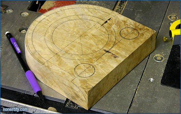
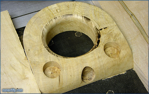
Now here I have laid out where my cuts and router edges will be. The
knob holes are laid out, the main arcs are defined, and the speaker hole
is penciled in. The ring that's outside the main speaker hole is
where the routered roundover bevel will stop. The wider arc on the
side is the profile of the control face of the amp, the wood will curve
down similar to my first amp.
Now that the arc is roughed out, I'll sand it smooth, till it's flush with
the pencil outline.
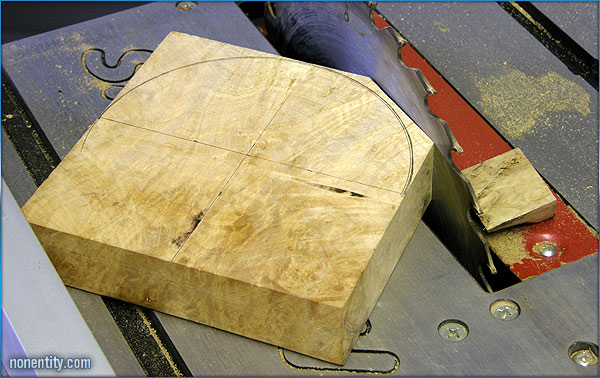
Cutting the main arc on the 6x6 amp. I don't have a scrollsaw, so I
have to whittle away
at the edges till they're ready to sand smooth.
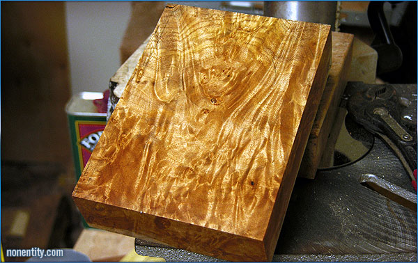
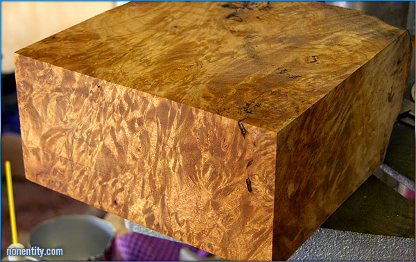
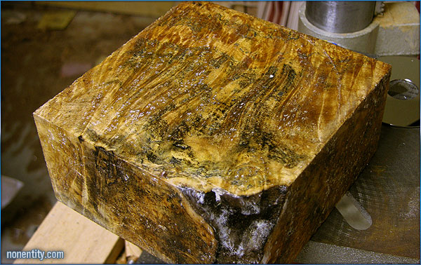
After selecting which piece was going to be my 4x6 amp, and shaving off
the part I don't need. There's a pattern just in the right spot to
provide grain that wraps around the speaker hole, and swath down like
drapes on either side. The grain is really going to turn out well on
this one. It'll be much prettier than the first amp. A quick
wash of mineral spirits really shows the figuring of this big leaf maple.
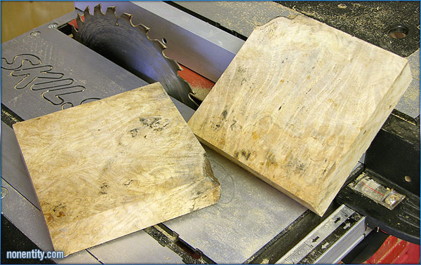
Here I split the main block into two halves. I had to do this in
several passes,
since my tablesaw blade wasn't tall enough to cut it all the way through
the middle.
I'll select one for my next 4x6 amp, and one for my 6x6 amp.
Absolutely beautiful! I can't believe what a difference a few close
shaves
with the tablesaw makes.
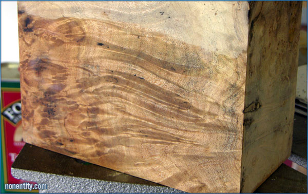
Each side of this block has very unique grain patterns. It's going
to be hard to
decide which side to keep, and which side gets hollowed out.
Here's my new amp or two. This is before I cleaned off all the wax they encase chunks like this in.
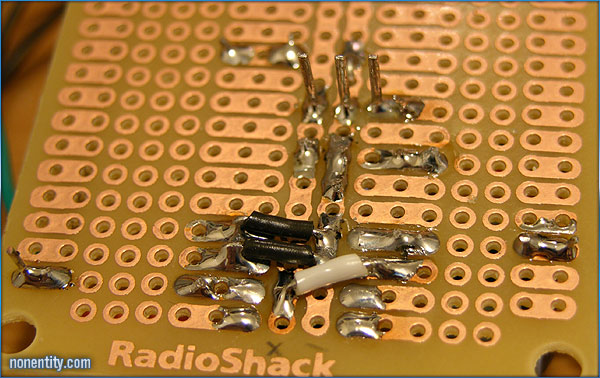
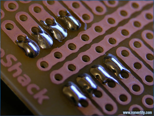
The back of the board, showing solder points.
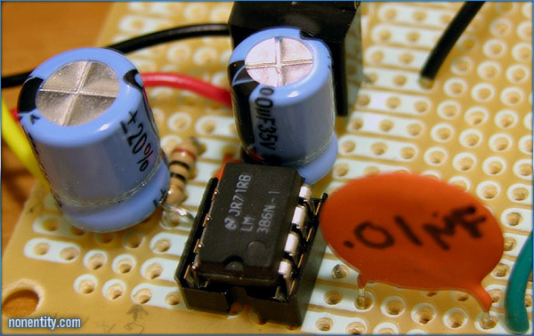
Main circuit all done! Note how compact it is. The previous
amp I did took up
most of the board. Now I can make two amps by cutting the board in
half.
This is the first of the components soldered in.
Here I have the socket for the lm386 audio amp soldered in.
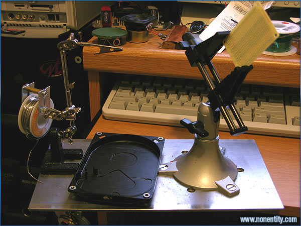
This is my solder station. Big chunk of steel from a FOROX animation camera,
drilled and tapped
to accept the bolts on the base of my Panavise. Also drilled and tapped
the base of the extra
hands Alligator clippy thing, and bolted it down so it doesn't move. The
solder reel is
assembled from screws and tubing, and the parts tray is a hard drive case.
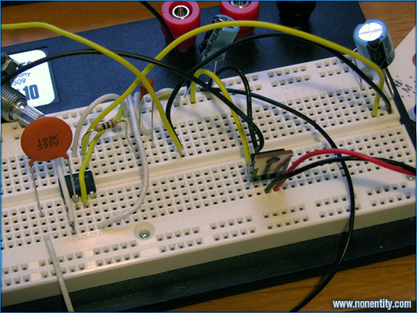
I did add a voltage regulator (12v) to the power side, because I plan
on the capability of a 9v AC
adapter jack in addition to the battery when I'm done.
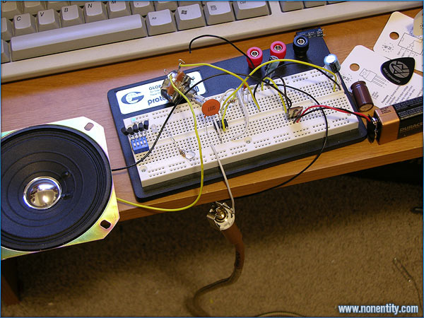
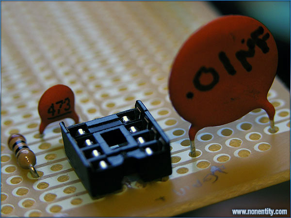
The amp circuit took about 15 minutes to assemble on the breadboard.
|