| 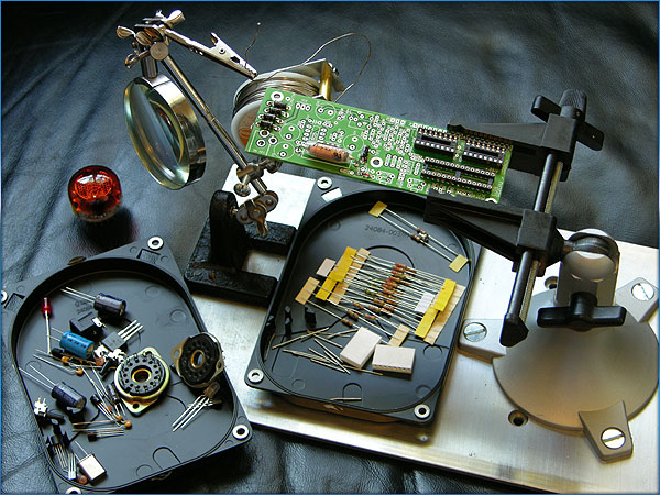
Here is the beginning of the
commissioned clock I am doing.
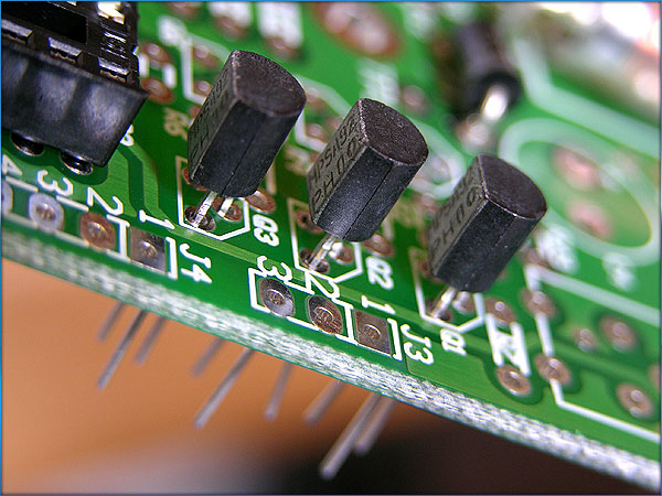
Getting the first set of transistors in place.
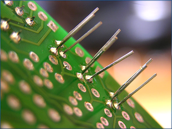
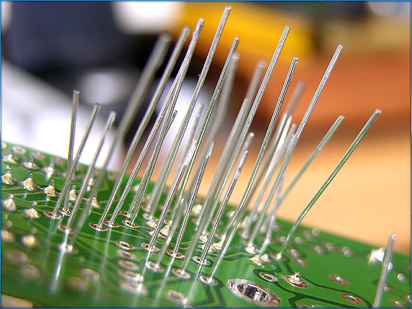
Transistor leads soldered, ready to clip the excess.
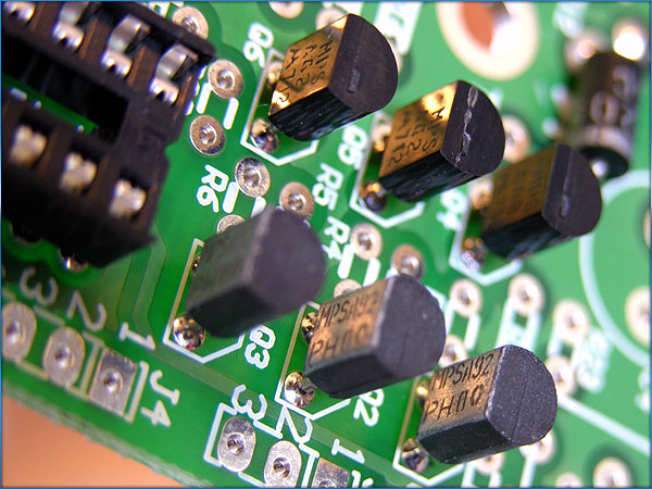
All the transistors set, soldered and done.
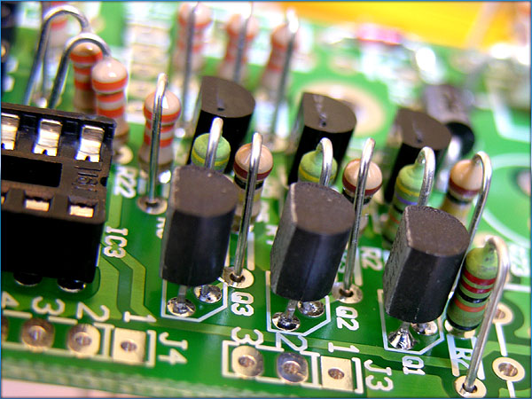
Placing the resistors, these are the most time intensive part of the circuitboard to complete. I have to make sure the values
are all correct and double check before I solder them into place.
Resistors all soldered in.
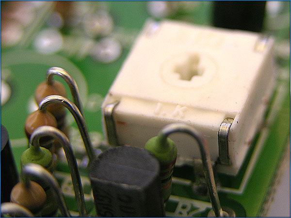
Now for the trim resistor. This is how
I adjust the voltage for the tubes. Once I power it up, I’ll have to
adjust this to somewhere between 170 and 180 volts DC. I usually set these to as close to 175 as I
can get it. It’s a very touchy
adjustment.
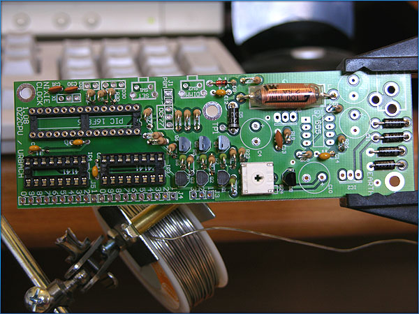
Wide shot of the board so far.
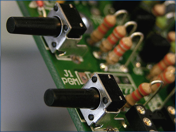
Set and Dimming buttons. These will
control the clock’s brightness and setting modes.
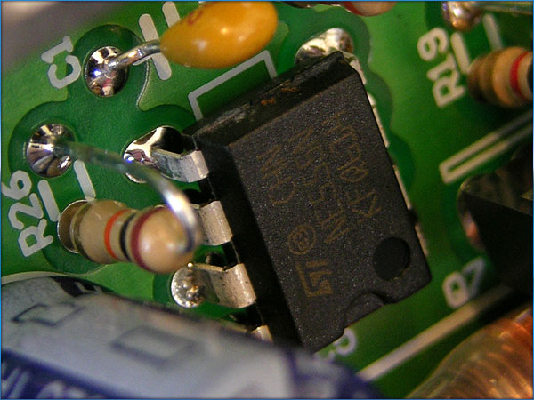
The 555 timer chip.
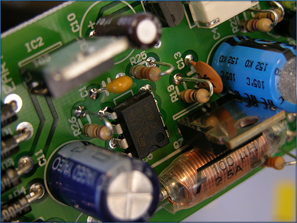
Timer chip, power transistor, regulator and large capacitors.
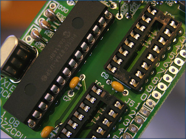
Beginning to set the PIC processor into its spot.
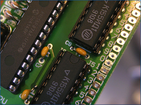
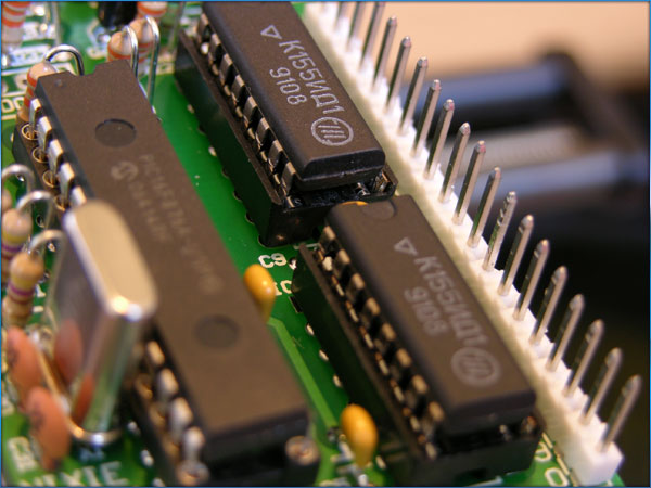
And now the Russian driver chips.
Normally, there would be six of these. One for each tube. But since we’re multiplexing these
tubes, we only need two.
Press fitting and then soldering the pinout
connectors for the wiring harness that connects the tubes to the board.
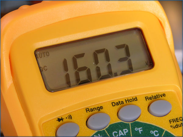
Power on! And it’s putting
out 160.3 volts DC. I will adjust
the trim resistor to 175 volts.
|